Blog

The grounding wire at home turned out to be this role.

A ground fault is the contact between a live conductor and a ground, a grounded metal enclosure, or a grounded component.

For example, the overhead conductor is broken, the power supply line is damaged, and the metal casing is damaged.
If the ground fault is not eliminated in time, some people may encounter a live conductor or metal casing, or the ground fault current will continue to exist, which may cause electric shock and equipment accidents or electrical fire accidents.

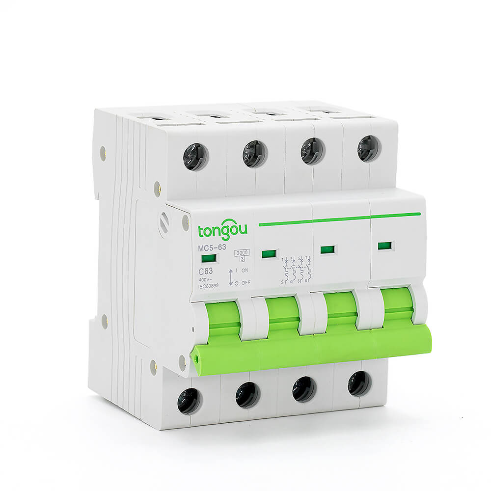
In the past, the ground fault protection was often protected by an miniature circuit breaker  (such as a fuse or a circuit breaker). When the ground fault current is greater than the operating current setting value of the overcurrent protection device, the circuit is cut off by the overcurrent protection device.

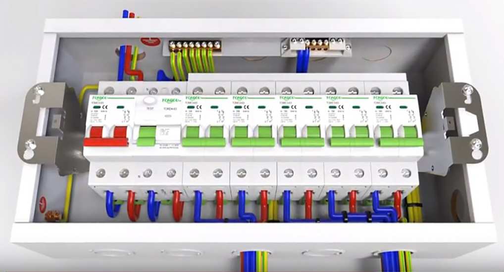
In the TT system, when the line with a large rated current and the distribution line are long, the fault current of the ground fault may be less than the set current of the protective device, and the rcb/rccb device will not operate.
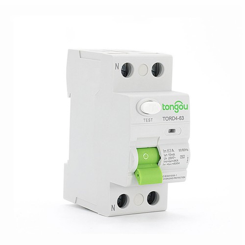
In this case, the residual current protection device (or circuit breaker with ground fault protection) should be used for ground fault protection.

Different leakage problems require different leakage protection

1-44In a TN system, the situation is similar to the TT system in the event of a ground fault with a live conductor landing or an incomplete metal ground fault or arc ground fault.
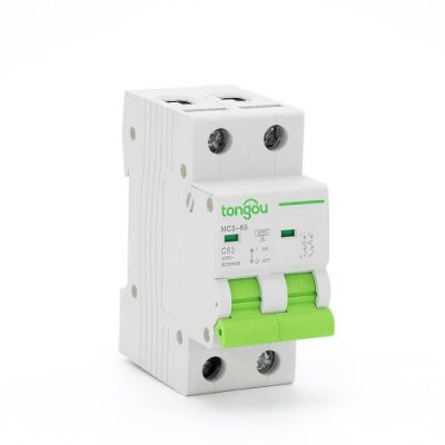
Even if the metality of the TN system is short-circuited to the protective conductor (PE line), the overcurrent protection device may not operate when the line is long and the rated current is large.

At this time, only the residual current protection device or the circuit breaker with ground fault protection can be used for reliable ground fault protection.

When the miniature circuit breaker  is only used for ground fault protection, the rated residual operating current or ground fault current can be from several hundred milliamperes to tens of amps or even hundreds of amps depending on the form and capacity of the power distribution network system.

In order to prevent unnecessary malfunction caused by transient faults, the break time should generally be delayed.

When the residual current protection device is used for ground fault protection and indirect contact protection is to be considered, the action characteristics should be selected according to the requirements of indirect contact protection.

Air breakdown voltage

The electrode 1 and the electrode 2 are an anode and a cathode, respectively, which are connected to the positive and negative electrodes of the battery. When the voltage is equal to zero, the circuit of course does not pass, and no current flows between the electrodes.

tomc5-63 3ka 110v 220v curve c 2p 63a mini circuit breaker mcb

We adjust the variable resistor R and gradually increase the voltage between the electrodes. We find that there is current flowing between the electrodes. This is because of cosmic rays. Cosmic rays break down air molecules, negative ions (electrons) after breakdown move to the anode, and positive ions move to the cathode. Since the cosmic ray density of the ground is essentially constant, the current between the electrodes is not large. We see a lot of voltage increase between the contacts, but the current is constant.

We continue to adjust the variable resistor and the voltage continues to increase. When the voltage crosses point B, the air begins to partially ionize by the action of the electric field force, and we see a slight increase in current. When the voltage reaches the Uc point, the air is broken down. The voltage Uc at this time is the breakdown voltage.

After the air is broken down, there is glow in the electrode gap, a very beautiful light:

timthumb

We continue to increase the voltage. We found that the voltage began to drop at this time, the current continued to increase, and the strong light appeared after the air ionization. We successively entered the D zone, the E zone and the F zone of the arc breakdown zone.

From point C to the right, the gas can be maintained by itself after the breakdown. We call this section the self-sustaining discharge zone; from C to the left, the gas cannot be maintained after the breakdown. This section is called the non-self-sustaining discharge zone.

The non-self-sustaining section is very interesting. Its breakdown voltage is affected by the air pressure. The lower the pressure, the easier it is to break down. At the same time, it is also affected by the distance of the electrode gap. The smaller the distance, the easier it is to break down. Therefore, the breakdown voltage Uc is a function of the product of the gas pressure p and the electrode gap d. Characterizing the air breakdown characteristic relationship is the Bashen curve.

About the arc and Let’s first get to know the arc

Let’s first get to know the arc:

This is the arc, and we see that the arc is a hot gas. Inside the arc, the temperature is as high as 3,000 degrees or more, and electrons will escape from the atoms to form negative ions, which are lost, so that all the air molecules become plasma, that is, a mixture of electrons and positive ionsvideo1-1024x482-1.

Circuit breaker opening distance:

We call the shortest distance between the moving contact and the static contact at this time called the open distance.

The purpose of the open distance is to ensure that the air between the moving and stationary contacts in the open state does not cause electrical breakdown.

Action characteristics of the electric switch

The leakage switch has two parameters: the operating current and the non-operating current.

Their meanings are as follows:

(1) Rated leakage current IΔn
The rated leakage operating current IΔn is the value of the leakage current that the leakage switch must operate under the specified conditions.

Generally, residual current device value ranges from 5 to 20000 mA, of which 30 mA and below are high sensitivity types, mainly used for human body protection; 50 to 1000 mA is moderately sensitive and is used for both human body Electric shock protection and leakage protection equipment fire protection; 1000 mA or more is low sensitivity, used for leakage fire protection and ground fault monitoring.

(2) Rated leakage non-operating current IΔn0
The rated leakage non-operating current IΔn0 is the value of the leakage current that the leakage switch must not operate under the specified conditions.
It is worth noting that the rated leakage non-operating current IΔn0 always appears in pairs with the rated leakage operating current IΔn, and its preferred value is: IΔn0=0.5IΔn.

Generally, the current from IΔn0 to IΔn is a section in which the operation cannot be confirmed. If a certain test current falls within this section, the leakage switch may or may not operate.

When using the above parameters, special attention should be paid to the current range from IΔno to IΔn. If the leakage protection device is required in the engineering design, it must act when the residual current passing through is greater than or equal to I1, and must not operate when the residual current passing through is less than or equal to I2. Therefore, when configuring and selecting the leakage protection device, it should be: I1≥IΔn And I2 ≤ IΔno.